

Use:
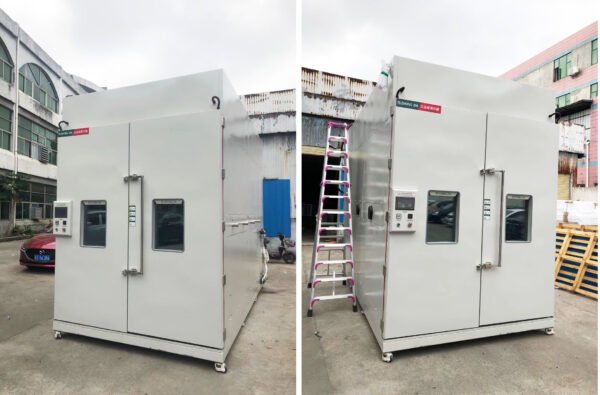
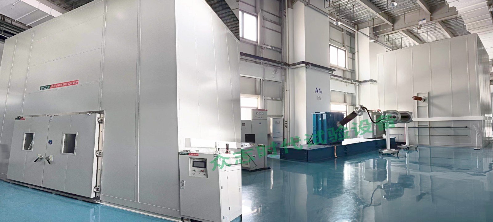
The equipment is suitable for the determination of power frequency withstand characteristics of porcelain and glass insulators used outdoors and exposed to polluted atmospheres in AC systems with a maximum system voltage range of 1kV to 120kV. These tests cannot be directly applied to oil-coated insulators and special types of insulators (insulators with semi-conductive glaze or insulators covered with any organic insulating material). The purpose of this test is to specify the artificial pollution test procedure applicable to overhead lines, substations, traction line insulators and bushings. The equipment is manufactured in accordance with the requirements of GB/T 18889-2002 and GB/T 4585-2004 artificial pollution test for high-voltage insulators for AC systems. The equipment includes a salt water supply tank, a salt water supply pump, a water supply pressure regulating device, a flow meter, a water supply pipeline, a compressed air supply system, a compressed air heating and filtering device, a compressed air regulating system, a spray nozzle, an exhaust pipe, an exhaust filter, a compressed air supply system, a high-voltage wall bushing, an insulator test rack, a switch cabinet, a contact voltage regulator, a pollution test transformer, a protective resistor, a capacitive voltage divider, an insulating support, a sealing test room, etc.
Product Details:


Major Specifications:
| Product Name | Multi-factor salt spray corrosion test device |
| Product model |
CZ-170KC |
| Nominal volume | 170m3 excluding the top sloping roof volume |
| Inner box size (mm) | 6300×4500×6000 W×H×D (excluding sloping roof height)
Note: The top sloping roof angle is 120°, and the sloping roof height is 1820mm |
| Outer box size (mm) | About 6500×6600×6700 W×H×D
Note: Excluding the size of the salt water tank and the size of the complete set of power frequency AC pollution test equipment |
| Medicine water tank size (mm) | About Φ1000×H 1300 |
| Switch cabinet size (mm) | 1200×2100×1100 W×H×D |
| Regulator size (mm) | 1450×1850×1400 W×H×D |
| Size of pollution transformer (mm) | 3300×2100×1600 W×H×D |
| Size of protective resistor, sub-container, insulating pillar (mm) | 3600×2100×850 W×H×D |
| Net weight of equipment | About 20 tons |
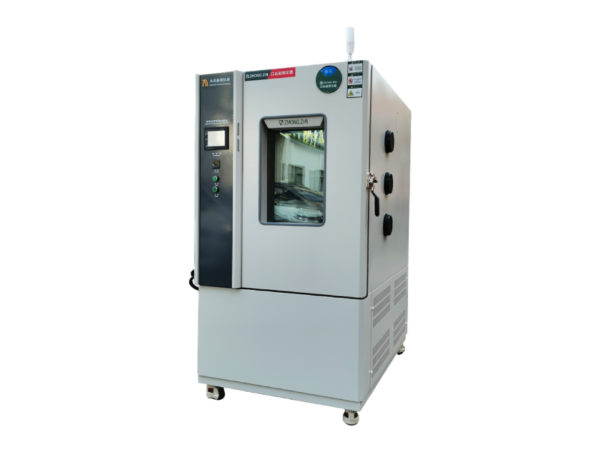
| Test environment conditions | Ambient temperature is +20℃, relative humidity ≤85%RH, and there is no sample in the test chamber (unless otherwise specified) |
| Test room temperature range | 5~40℃
Note: The test room temperature is not controlled and is determined according to the ambient temperature |
| Saturated barrel temperature range | RT~63℃
Note: During the test, the saturated barrel temperature is set 12℃ higher than the test chamber temperature but not higher than 15℃ |
| Technical indicators of power frequency pollution complete set test device | Rated capacity: 500kVA
Rated current: 4.16A Rated voltage: low voltage winding: 0.6kV (using 2 groups in series and parallel) high voltage winding: 120kV (low voltage winding in parallel) 60kV (low voltage winding in series) Rated current: low voltage winding 833.3A high voltage winding 4.16A Phase number: single phase Frequency: 50Hz Short circuit impedance: ≤3% Running time: At rated capacity and rated voltage, continuous operation is allowed for 60min, and at 80% rated capacity and rated voltage, continuous operation is allowed. Reliable grounding bolts are provided, and the grounding point has obvious grounding symbols or grounding words. The outer surface is coated with insulating paint for protection. |
| System principle of power frequency pollution sleeve test device | K1: power switch cabinet
TY: contact voltage regulator B1: test transformer C1 C2: capacitor voltage divider R: protective resistor KZ: control device
|
| Brine supply flow rate | During the test, the solution flow rate of each sprayer is 0.5 L/min±0.0 5L/min, and the total flow rate tolerance of all sprayers should be ±5% of the nominal value |
| Number of nozzles | 18 pieces |
| Reference test method | GB/T 18889-2002 Humidity test and salt spray test
GB/T4585-2004 Artificial pollution test for insulators for AC systems GB/T16927.1-1997 High voltage test technology Part 1 General test technology GB/T16927.2-1997 High voltage test technology Part II Measurement System JB/T9641-1999 Test Transformer JB/T8749.8-2014 Column Voltage Regulator GB 1094.1-2013 Power Transformer Part I General GB 1094.2-2013 Power Transformer Part II Temperature Rise of Liquid-Immersed Transformer GB 1094.3-2003 Power Transformer Part III Insulation Level, Insulation Test GB 1094.5-2003 Power Transformer Part V Ability to Withstand Short Circuit JB4705 -1992 Coupling Capacitor and Capacitive Voltage Divider GB/311.1-2012 Insulation Coordination of High Voltage Transmission and Transformation Equipment |
| Nozzle Installation Reference | GBT 4585-2004 Typical Structure Diagram of Sprayer Nozzle |
| Noise | Less than 70db(A) (measured 1m from the box and 1.2m from the ground) |
| Power cable | The power supply cable and main power switch are located behind the electric control box. |

Reviews
Clear filtersThere are no reviews yet.